⚡ Conexionado Variador MX2 -
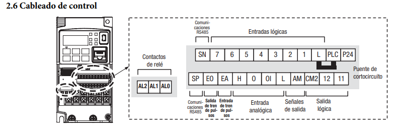
➡️ Conexionado Omron MX2 Clásico:
🔹Cableado de control:
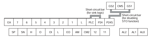
➡️Conexionado Omron MX2 EV2:
🔹Cableado de control:
¡ IMPORTANTE! - La entrada CMS del variador hay que conectarla a negativo, es decir 0v, de lo contrario el STO no funcionará y el variador nunca se pondrá en RUN.
 i
i
🔹
➡️ Diagrama completo:
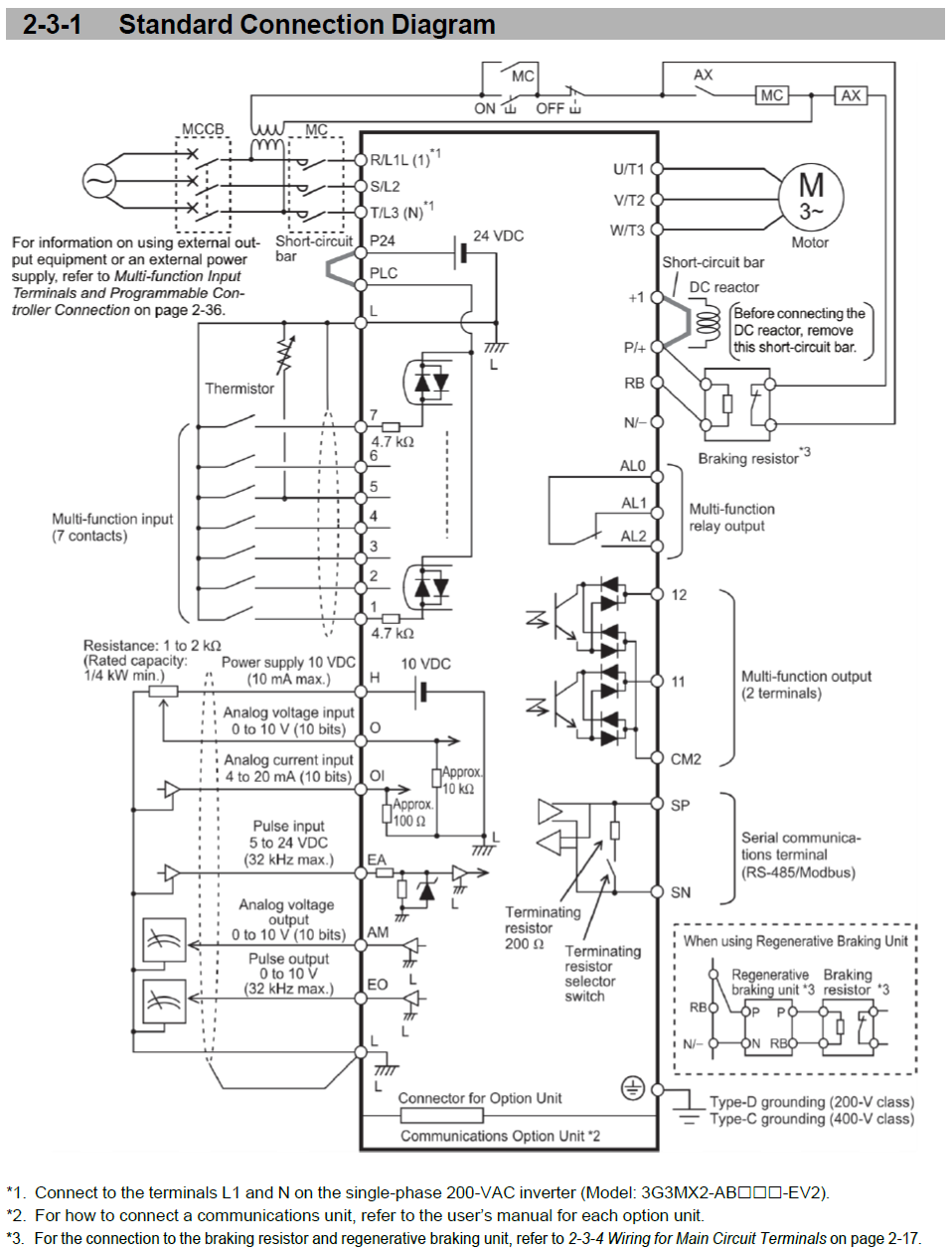
!Importante! en este modelo, hay que cablear la entrada CMS a negativo, 0v,Descripción de lolas contrarioentradas noy funcionarásalidas eldigitales:
STO.
| Item | Terminal symbol | Terminal name | Description | Specifications |
|---|---|---|---|---|
Analog Power supply | L | Input signal | Common terminal for the internal common power supply, digital input, and analog I/O terminals. | — |
H | Frequency reference power supply | 10 VDC power supply for terminal O. | Allowable current: 10 mA max. | |
Frequency setting input (Analog voltage input) | O | Frequency reference input | 0 – 10 VDC analog voltage input (adjustable max. at 9.8 V). | Input impedance ≈ 10 kΩInput range −0.3 – +12 VDC |
Frequency setting input (Analog current input) | OI | Frequency reference input | 4 – 20 mA DC analog input (adjustable max. at 19.8 mA). | Input impedance ≈ 100 ΩInput range 0 – 24 mA |
Sensor input (TH) | 5 | External thermistor input | Multi-function input 5 set to 19 (TH: PTC thermistor). Trips if thermistor ≥ 3 kΩ. | PTC type |
Output | AM | Multi-function analog output (Voltage) | 0 – 10 VDC analog output. | Allowable current: 2 mA max. |
| Item | Terminal symbol | Terminal name | Description | Specifications |
|---|---|---|---|---|
Digital Power supply | L | Input signal | Common terminal for the internal common power supply, digital input, and analog I/O. | — |
P24 | Input signal power supply | 24 VDC power supply for contact input signal. | Allowable current: 100 mA max. | |
P24S | Safety input signal power supply | 24 VDC for safety switch contacts (source logic only). | Allowable current: 100 mA max. | |
PLC | Input terminal power supply | Sink logic: short to P24 / Source logic: short to L. | External supply via removed bar. | |
CMS | Safety input signal common | Common for safety input terminals. | — | |
Inputs 1–7 | 1 – 7 | Multi-function inputs | 7 functions selectable from 66, for sink or source logic. | ON ≥ 18 V, OFF ≤ 3 V27 VDC max, 5 mA load @ 24 V, 4.7 kΩ int. res. |
Safety input | GS1 / GS2 | STO input terminals | Safe torque-off inputs. | ON ≥ 15 V, OFF ≤ 5 V27 VDC max, 5.8 mA @ 27 V, 4.7 kΩ int. res. |
| Item | Terminal symbol | Terminal name | Description | Specifications |
|---|---|---|---|---|
Digital Input | EA | Pulse input – A | Frequency setting pulse input (5–24 VDC). | Pulse ≤ 32 kHz10 kΩ int. res.ON ≥ 4 V, OFF ≤ 1 V, 27 VDC max |
EB (7) | Pulse input – B | Set C007 = 85 (EB: rotation direction detect). | Pulse ≤ 32 kHz4.7 kΩ int. res.ON ≥ 18 V, OFF ≤ 3 V | |
Outputs 11–12 | 11 / 12 | Multi-function outputs | Two functions selectable from 47. Sink or source logic. | Open collector output27 V max, 50 mA max, 4 V drop max |
Safety monitor | 11 (EDM) | Safety monitor output | Enabled when EDM switch is ON (safety monitor signal). | — |
Common output | CM2 | Output signal common | Common terminal for 11 and 12. | 100 mA max. |
Relay outputs | AL1 / AL2 / AL0 | Relay output terminals | Selectable functions (47 options). SPDT contacts. Default: NC AL1–AL0, NO AL2–AL0. | AL1–AL0 250 VAC 2 A (R) / 0.2 A (L)AL2–AL0 250 VAC 1 A (R) / 0.2 A (L)Min. 100 VAC 10 mA, 5 VDC 100 mA |
¡ IMPORTANTE,